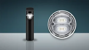
A draw-activated disposable can produce vapor during a quick bench check and still be unsuitable for production. “It fires” answers only one question. Buyers also need to know how much draw is required, whether the device remains active through a normal inhalation profile, when it stops, whether results are repeatable, and whether pressure changes or contamination can trigger it without an intended draw.
A useful disposable vape draw-activation test therefore treats the device as a controlled input-and-response system. The input is a defined pressure differential or airflow condition. The response may include activation time, output duration, cutoff behavior, indicator response, and evidence of a false trigger. This approach turns subjective comments such as “too hard to pull” or “too sensitive” into a qualification method that a supplier, buyer, and inspection team can repeat.
What the Test Must Separate
The activation system should not be judged as one pass/fail event. Four behaviors need separate treatment.
Activation threshold is the minimum controlled draw condition that produces the agreed response. Holding behavior describes whether activation remains stable while the draw continues. Release and cutoff behavior describe how quickly the device stops after the draw ends and whether the programmed maximum duration works as intended. False-trigger screening checks whether handling, pressure disturbance, leakage into the air path, or other non-use conditions can activate the device.
These are related, but they are not interchangeable. A very sensitive device may start easily yet be more vulnerable to unintended activation. A device with a conservative threshold may resist false triggers but feel inconsistent if normal users cannot activate it reliably. The buyer’s task is to define an acceptable operating window, not simply demand the lowest possible threshold.
Measure the Input, Not the Operator’s Impression
A person taking repeated puffs is not a measurement system. Draw strength, ramp rate, duration, mouth seal, pauses, and operator technique all change from attempt to attempt. Human trials can help describe usability after an engineering screen, but they should not be the primary release method.
A repeatable fixture should apply a controlled draw to the device inlet while recording the relevant pressure differential or flow condition. Pressure and airflow are related, but they are not the same measurement. Honeywell’s pressure and airflow sensor guidance explains why sensor type and calibration basis must match the quantity being measured. The test record should therefore state what the fixture controls, where it measures, the units used, and how the device is sealed to the fixture.
The setup should include:
- A stable vacuum or flow source with suitable adjustment.
- A calibrated pressure or airflow sensor with adequate resolution for the intended range.
- A leak-resistant adapter that does not obstruct the device inlet.
- A method for detecting activation, such as electrical output, optical indicator response, or another defined signal.
- A timer or data-acquisition method capable of capturing start, release, and cutoff behavior.
- A fixture drawing or photograph showing the connection and measurement point.
Do not copy a threshold from another product simply because both devices are draw activated. Air-path geometry, sensor placement, inlet restriction, firmware logic, coil and oil system, and intended user experience can all change the appropriate operating window.

Lock the Test Conditions Before Comparing Samples
Small setup changes can create large apparent product differences. Before testing, define device orientation, state of charge, filled or unfilled condition, oil type where applicable, temperature, conditioning time, inlet adapter, draw ramp, hold time, recovery time, and number of repetitions.
Filled and unfilled hardware may behave differently because oil loading, seals, condensation, and pressure pathways change the system. If production units will be filled, a dry engineering sample alone cannot prove filled-device performance. Any filled test should use an approved material and controlled process; it should not invent an oil specification or filling condition that was never agreed with the buyer.
The measurement system also needs evidence that it can distinguish meaningful differences. NIST’s measurement-process guidance emphasizes repeatability, reproducibility, stability, calibration, and uncertainty. For a practical supplier program, that means the same sample should not appear to move in and out of specification merely because the operator, adapter, or fixture changed.
Build a Test Sequence Around Real Failure Modes
Start with a baseline inspection. Record the model, revision, lot, sample ID, charge condition, visible air-inlet condition, and any previous use. Confirm that the inlet is not blocked and that the adapter seals without deforming the enclosure.
1. Threshold sweep
Increase the controlled draw gradually or apply defined steps until activation occurs. Repeat the sequence after an agreed recovery period. Record the measured input at activation rather than reporting “light,” “medium,” or “hard.”
2. Normal operating window
Apply several draws within the approved normal range. Check activation consistency, response delay, stability during the hold period, indicator behavior, and shutoff after release. The objective is not to maximize vapor in the fixture. It is to confirm that the agreed input produces a repeatable response without dropout or delayed release.
3. Marginal-input challenge
Marginal inputs reveal what threshold sweeps miss: test just below and just above the intended lower boundary. This helps reveal units that chatter, activate intermittently, or depend on an unusually sharp ramp. A marginal challenge should be used for characterization and guard-band decisions, not quietly substituted for the normal acceptance test.
4. Maximum-duration and cutoff check
Apply a draw long enough to reach the programmed limit when that function is part of the design. Verify the cutoff response and the required reset or recovery behavior. Do not infer the programmed limit from a single unit; compare results with the approved product specification.
5. Repeated-draw recovery
Run a defined sequence of draws with controlled intervals. Watch for missed activations, progressively delayed response, abnormal heating, indicator errors, or a device that remains active between cycles. The sequence must stay within the approved product-use and laboratory-safety limits.
False-Trigger Screening Needs Its Own Protocol
A device that passes intended-draw testing can still activate when it should remain off. False-trigger screening should be risk based and should reproduce credible disturbances without pretending to prove every shipping or storage condition.
Useful screens may include controlled pressure transients, orientation changes, fixture handling, gentle vibration, air-inlet obstruction and release, and testing before and after approved environmental or transport conditioning. If filled devices are used, inspect whether condensation, leakage, or contamination has entered the sensing path. The disturbance, exposure, duration, and observation method must be documented.
This test is not permission to improvise dramatic abuse. It should be linked to a defined failure hypothesis. For example: can a pressure pulse across the inlet start the device; can liquid in the air path cause a sustained signal; or does the device fail to release after the disturbance ends? Shipping-carton validation, battery-safety evaluation, and regulatory compliance remain separate activities.
With threshold, holding, release, and false-trigger behavior each characterized, the remaining step is turning results into a pass/fail decision.
Define Acceptance Rules Before Seeing the Data
The supplier and buyer should approve the decision rules before qualification or lot release. Otherwise the limits tend to move after failures appear.
A complete rule set should identify:
- The controlled input range and measurement units.
- The required activation rate within that range.
- Maximum allowed response delay, dropout, or release delay where relevant.
- The programmed cutoff expectation and reset behavior.
- The number of repetitions per sample and sample quantity per lot.
- Which outcomes are critical, major, or minor defects.
- Whether any false trigger is an automatic failure or requires a defined confirmation sequence.
- Retest, segregation, investigation, and disposition rules.
- The product, firmware, sensor, air-path, and process changes that require requalification.
Avoid publishing a universal numeric threshold unless it is supported by an approved model specification and validated method. A defensible requirement is model specific: it states the measurement setup, operating window, sample plan, and decision rule together.
Connect the Result to Purchasing and Production Control
The approved test method should be referenced by the product specification, golden sample or engineering approval record, quality agreement, control plan, and pre-shipment release checklist. The supplier should record equipment identity, calibration status, software or firmware revision where relevant, sample IDs, raw results, failures, deviations, and disposition.
This is also where the article’s commercial paths must remain accurate. Buyers comparing custom AIO architecture, samples, and factory programs can review AIO samples and White Label production. Buyers looking for stock-led products available for direct ordering should use disposable hardware available to buy online. Those destinations serve different purchasing intents and should not be described as interchangeable inventory pages.
Before tooling or program approval, the related decision guide on button vs draw-activated AIO hardware helps establish whether automatic activation is the right architecture. Where airflow qualification is the broader concern, the 510 cartridge airflow qualification guide explains why the air path must be treated as a measured system rather than a thread-only compatibility check.
Buyer Review Checklist
- Confirm that the test controls pressure differential or airflow in stated units.
- Confirm that the fixture connection does not alter the inlet restriction.
- Separate threshold, holding, release, cutoff, and false-trigger criteria.
- Define conditioning, orientation, charge state, fill state, and recovery time.
- Use traceable samples and record model, lot, hardware revision, and firmware where applicable.
- Predefine sample size, repetitions, defect classification, and disposition.
- Require requalification after relevant sensor, firmware, air-path, enclosure, or process changes.
- Link the approved method to the purchase specification and shipment-release record.
Final Takeaway
The best method controls the input, separates intended activation from release and false-trigger behavior, and produces repeatable records that can survive a supplier change, engineering revision, or lot dispute.
For ILEVA buyers, the practical next step is to decide which commercial route fits the program: evaluate AIO samples and White Label production for custom factory work, or review disposable hardware available to buy online when current stock and direct ordering are the priority.